GO device logging
GO devices use intelligent patented logging algorithms to decide when to record speed, position, and other engine information. The device is constantly monitoring various inputs, for example: second-by-second GPS data, hundreds of accelerometer readings per second, and engine diagnostic inputs. The device monitors the data and determines the appropriate time to store a value.
Various data loggers exist on the market today that use a simple time- or distance-based logging algorithm. These approaches, though simple, have significant drawbacks:
Important high or low values for speed (or other metrics) could be missed.
Positions during cornering are missed (producing inaccurate mileage or poor display on map).
Increased data costs by logging redundant information (for example, recording data for a vehicle that is not moving or moving in a straight line at a constant speed).
Logging Accurately
The main concept behind GO device logging is to produce an accurate representation of the original data by logging the essential points on a graph and discarding redundant points. We sometimes refer to this as curve-based logging. This is best illustrated by example:
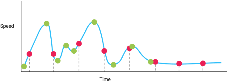
In this graph, the actual trip is represented by the blue curve. The red dots represent a simple time-based sampling where a speed value is recorded at regularly spaced time intervals. Notice how some high points and low points are missed by this approach. Also notice that, even when the speed does not change, the time-based approach continues reading the same value.
The green dots represent a more accurate record of the data by establishing the ideal way to reproduce the data with the fewest number of data points. This is the basic principle that underpins the intelligent logging of the GO device.
Position and Speed
The GO device monitors both position and speed at the same time, using the approach discussed above, to log the data. By doing so, the speed profile can be very accurately reproduced and the location of the device determined. This also means the trip will be logged properly around corners (yielding a very accurate mileage calculation).
Engine Diagnostics
The GO device also monitors key engine diagnostic values and applies the approach above to log these values (data such as RPM curve, fuel level and many other parameters) in an optimized manner that allows an accurate reproduction of events without the drawbacks associated with time- or distance-based logging.
Note: The intelligent logging approach means the rate at which the data is logged will vary; we cannot specify a fixed logging rate such as “x times per hour” because the logging rate depends on the driving behaviour of the vehicle. The GO device will log as as many times as required to accurately represent the data being recorded while minimizing redundant data.
Technical Details
The methodology used to determine the optimal time to log GPS points is a curve-based algorithm that utilizes the Ramer-Douglas-Peucker (RDP) algorithm. The purpose of the RDP algorithm is to create a simplified curve compared to the original data. This is done by removing trivial and redundant data points, and keeping only the relevant data points within the allowable error limit. The curve-based algorithm is used to determine which of the second-by-second GPS points need to be saved and transmitted to MyGeotab. The curve logging algorithm allows the GO device to keep only the points that are necessary in order to provide an accurate representation of the events logged. Accuracy is dictated by the predetermined allowable curve error values.
When the algorithm runs on the set of data points, it starts with the first and last points in the data set and automatically marks these as to-be-saved. It then considers the points between the first and last points; the data points will be continually divided until a line segment within the allowable error limit is obtained; this point will then be marked as to-be-saved. The algorithm will then run again for any points between the first point and the new point as well as any points between the new point and the last point.
The curve-based algorithm is run first on Latitude vs. Longitude and then on Speed vs. Time. The curve algorithm is run on speed values between the to-be-saved points predetermined by running the curve on position.
Based on the curve reduction method and the chosen allowed error values, the requirement is that the data between two saved GPS points will be acceptably linear in both position and speed.
GPS Logging
The curve algorithm is run on the data in the following cases:
The curve buffer becomes full.
The actual position of the GO device differed excessively from the predicted position of the GO device.
Another event triggered the running of the curve.
Below is a list of parameters that utilize the curve algorithm for data logging.
Engine Data Logging
Curve Logging on Engine Data
Where appropriate engine data is logged using the curve-based algorithm. The following is a list of the engine data now logged using the curve-based logic:
Battery Temperature
Brake Lining Remaining
Brake Temperature
Cab Interior Temperature
Charge State
Coolant Level
Coolant Temperature
Cruise High Speed Limit
Engine Cooling Fan Speed
Engine Oil Level
Engine Oil Life Remaining
Engine Oil Pressure
Engine Oil Temperature
Engine Speed
Fuel Alcohol Composition
Fuel Filter Life Remaining
Fuel Level
Maximum Road Speed Limit
Outside Temperature
Starter Brush Life Remaining
Starter Current
Tire Pressure
Transmission Oil Level
Transmission Oil Temperature
Washer Fluid Level
Vehicles will not necessarily return all of the above information; the list is based on all the supported engine protocols.
Total Fuel Used
“Total fuel used (since telematics device install)” is generic status data. No matter how fuel information is received from a particular vehicle, be it OBD2, J1708, J1939 or another diagnostic standard, a generic Total Fuel Used record will be saved after ignition off. An additional record, “Total fuel used while idling (since telematics device install)”, which is the fuel used while road speed is 0, is also saved on ignition off. “Total fuel used (since telematics device install)” (KnownId DiagnosticDeviceTotalFuelId) and “Total fuel used while idling (since telematics device install)” DiagnosticDeviceTotalIdleFuelId are the diagnostics used to track fuel consumption.
Seat Belt and Odometer
Seat belt and odometer requests are proprietary on most passenger cars. It is Geotab’s goal to support seat belt and odometer across all the major vehicle manufacturers. If you are unable to obtain seatbelt or odometer requests for your vehicle, please contact Geotab Support. You can query the percentage of seat belt, odometer and other engine based data is supported for different vehicle types via MyAdmin.
Seat belt use is logged on status change: a value of 1 represents the seat belt unbuckled, while a value of 0 represents the seat belt buckled. Odometer is logged both on ignition on and ignition off and every hour.
Engine Hours
It is often important in fleet tracking to look at a vehicle’s engine hours. While Geotab strives to support this data on as many vehicles as possible, it is sometimes not possible. As a workaround, Geotab provides two types of engine hours StatusData. It is important to distinguish between the two in order to utilize them appropriately.
DiagnosticEngineHoursId:
This is the engine hours provided by the ECU in the vehicle as read by the GoDevice. This is reported every hour and at ignition OFF.
DiagnosticEngineHoursAdjustmentId:
Records the GPS travel time for vehicles which do not report engine hours from their ECU. An engine hours record can also be manually added which will then report as total GPS travel time added to the manually entered value. When the manual engine hours entry is updated, the total GPS travel time used in the calculation is reset to zero before continuing to increment.
Add<StatusData><DiagnosticEngineHoursAdjustmentId> is used to add manual engine hours entries.
Get<StatusData><DiagnosticEngineHoursAdjustmentId> returns a calculated engine hours value based on GPS Travel time and the last reported engine hours value (either reported by the GoDevice or manually entered).
Odometer
It is often important in fleet management to track a vehicle’s odometer. While Geotab strives to report data as frequently and on as many vehicles as possible, this is not always possible. As a workaround, Geotab provides three types of Odometer StatusData. It is important to distinguish between the three in order to utilize them appropriately.
Odometer Status Data:
DiagnosticOdometerAdjustmentId:
This is calculated 2 ways based on whether the vehicle is reporting ECM Odometer or not.
- ECM Based Odometer:
Calculated as the ECM odometer reading, plus the GPS distance recorded since ECM odometer was last reported. - GPS Based Odometer:
When no ECM odometer data is being recorded, Odometer Adjustment will be reported as the GPS odometer reading.
Add<StatusData><DiagnosticOdometerAdjustmentId> is used to add manual Odometer entries.
Get<StatusData><DiagnosticOdometerAdjustmentId> Is used as shown below:
- If an individual device Id is provided, this returns a calculated Odometer value based on the last known DiagnosticOdometerId or Diagnostic OdometerAdjustmentId + GPS Distance.
- If no device Id is specified, this returns all DiagnosticOdometerAdjustmentId records in the date range (if provided).
DiagnosticRawOdometerId:
This is the raw value of odometer as reported by the vehicles ECU. When possible, this is reported every Ignition ON, Ignition OFF, and every 2km in between.
DiagnosticOdometerId:
This is a corrected odometer reading based on the raw odometer value and the odometer manipulators. It is calculated as Odometer = [Raw Odometer * Odometer Factor] + Odometer Offset.
Odometer Manipulators:
Note: If applied, these manipulators will only affect future DiagnosticOdometerId records. They cannot correct existing records.
Odometer Factor:
Used as a multiplier to correct raw odometer. As default this is set to 1 and can only be changed via the API. This variable is rarely used.
Odometer Offset:
This value gets added to Raw Odometer before it is saved as a DiagnosticOdometerId record. It can be set directly via the API, or MyGeotab can calculate it automatically if an odometer value is entered on the Vehicle Edit page.