IO Expander Protocol
General Description
The GO device and Input-Output Expanders (IOX) are connected in a dedicated CAN network. All communication is between the GO device and any connected IOXs - in particular, IOXs do not communicate with other IOXs. The following communication scenarios exist: GO device to all connected IOXs; GO device to an individual IOX; and an individual IOX to GO device. Readers are encouraged to look at examples from CAN IOX Sample Communication Session as they read through the rest of this page.
Identification
This document describes the IOX Expander Protocol version 1.2.
All messages since IOX Expander Protocol version 1.0 are supported, unless stated otherwise.
Interoperability
Third-party IOX Add-ons rely on the messages and protocols defined in this document to properly communicate with Geotab firmware. Geotab will endeavor to maintain support for the currently-documented messages and protocol. However, from time to time, Geotab may make changes to such messages and protocols which can potentially impact third-party IOX Add-on implementations. If Geotab makes any such changes, Geotab will use commercially reasonable efforts to provide partners with as much notice of the impending firmware changes as is practical given the circumstances. Geotab accepts no responsibility or liability for third party IOX Add-ons which fail to function properly, or at all, and any and all damages which arise, directly or indirectly, from such failures.
Geotab recommends that all partners who develop their own IOX Add-ons ensure they have the ability to remotely update their firmware. This can be accomplished by sending an update to the IOX Add-on using the MIME passthrough messages.
Serial Number
Each custom IOX is assigned a 4-byte Serial Number by the integrators, similar to each car having its own VIN. The 2 Most Significant Bytes of the Serial Number are reported in bytes 3 and 4 of the Poll Response (0x02). The 2 Least Significant Bytes are used to differentiate each IOX connected to the same CAN bus (attached to the same GO device) when the GO device is sending messages targeted for a specific IOX. In other words, the 2 LSB serve as the Address ID, and are included in bits 15 - 0 of the Arbitration ID.
Integrators are free to leverage any mechanism for the Serial Number assignment to each individual IOX, but Geotab recommends following the process outlined below:
- Generate a random 4 byte value.
- Make sure that the 2 LSBs are not equal to ‘0000’.
- Make sure that you do not already have this value stored in your database of existing serial numbers.
Message Structure
Message identification is done with an arbitration ID.
The Arbitration ID Field for IOX Messages:
| Bits | 29 to 24 | 23 to 17 | 16 to 1 |
|---|---|---|---|
| Contents | Reserved: 0 | Message: 0–127 | All IOXs: 0 Individual IOX Address ID: 1–65535 |
0x1F800000 IO_EXPANDER_RESERVED_MASK
0x007F0000 IO_EXPANDER_COMMAND_MASK
0x0000FFFF IO_EXPANDER_ID_MASK
Address ID
The last 2 bytes of the IOX Serial Number (MSB first) are used as the Address ID. This allows the GO device to identify the source of a message or, when the message is sent from the GO device, to identify the destination IOX.
The GO device sends messages with ID 0x0000 meant for all IOXs, or with an ID between 0x0001 and 0xFFFF when it is targeted at a specific IOX.
IOXs always use their own ID when sending messages. They never send 0x0000. For this reason, IOXs are not produced with Serial Numbers ending in 0x0000.
IOX ID
Each model of IOX is assigned an IOX ID by Geotab, similar to each model of car having a model name. Integrators shall contact Geotab to get an IOX ID assigned. The IOX ID does not need to be included in the IOX Serial Number. Integrators shall report the IOX ID in byte 7 of the Poll Response (0x02).
Acknowledge Process
- Each IOX should receive an ACK from the GO device for every message sent. If an ACK is not received within 150 ms, the IOX should repeat the message before sending anything else.
- The IOX must respond to the poll request within 500 ms.
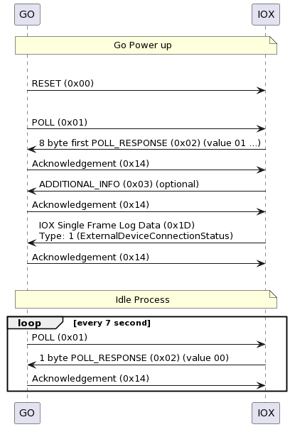
Polling
After powering up, the GO device will poll all IOXs every 7 seconds. Each IOX must respond to this poll by obeying the ACK rules. Unless otherwise described, most commands can only be sent after the first poll (handshake) is completed with the GO device.
Device Removed
If the GO device fails to detect an IOX that used to be connected (that is, the IOX was disconnected), the GO device will remove the IOX from its internal database after 5 attempts (35 seconds) and will make the slot available for a new IOX that can be connected at any time.
New Device
Any IOX that is connected to the GO device must respond to the poll request. The GO device will notice the new IOXs and add them to its internal database.
Undocumented messages
An IOX could receive messages from the GO device that are not documented here. The IOX must be capable of handling this situation by ignoring/discarding the unknown messages.
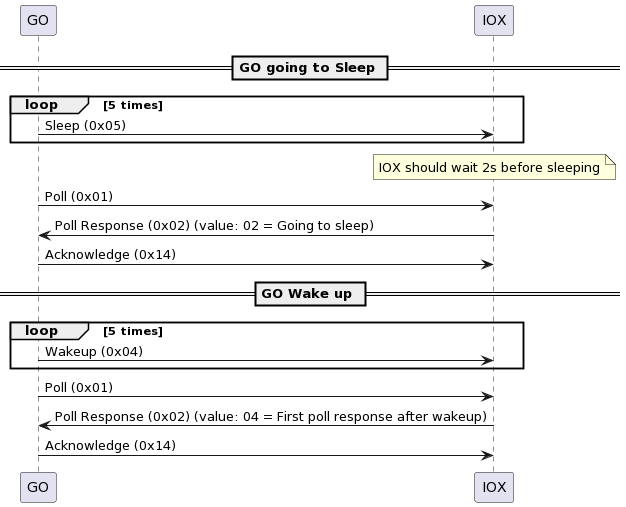
Waking up the GO Device
Every 1 second, the GO wakes up for 2 ms to look for CAN activity on the IOX bus. The IOX can wake up the GO by sending an RX Data (0x0C) message every 1 ms until the GO device notices the activity and sends the Wakeup (0x04) message to the IOX.
Commands
Reset (0x00)
Directed to all devices. Instructs all devices to reset and behave as if they have just powered up. IOXs should discard any setup information they might have received, de-assert hardware control lines, and open their relays.
Poll (0x01)
Sent by the GO device in a broadcast fashion to all units to check if they are there.
Poll Response (0x02)
Sent by an IOX when a poll is received. The ACK procedure must be obeyed. The first poll response after powerup (when Byte 0 Bit 0 is 1) contains all 8 bytes. All subsequent poll responses (when Byte 0 Bit 0 is 0) only contain the first byte.
Payload — Poll Response
| Byte # | Byte Description |
|---|---|
| 0 - Bit 0 | 0 = Have been polled before. 1 = First poll after power up. |
| 0 - Bit 1 | 0 = Not Going to Sleep. 1 = Going to Sleep. |
| 0 - Bit 2 | 0 = Normal reply. 1 = First poll response after wake up. |
| 0 - Bit 3-7 | Reserved |
| The following Bytes are sent only on first poll-response | |
| 1 | Firmware Version Major |
| 2 | Firmware Version Minor |
| 3-4 | 2 Most significant bytes of Serial Number |
| 5 | Reset Reason 0 = Power On Reset 1 = Reset Command 2 = New Firmware All others reserved. |
| 6 | Reserved |
| 7 | 150 to 199 IOX ID. Please contact Geotab to get one assigned. |
When the "Go to Sleep" command is received, but before actually going to sleep, the devices will indicate they are going to sleep through the indicated bit. This bit is cleared on wakeup.
Additional Info (0x03)
Sent by the IOX after an ACK for the first poll is received. This message is not strictly required for operation. However, sending of this message is required if any version information is to be reported, including: Product, Hardware, Firmware Major, Firmware Minor, or Version Control.
Payload — Additional Info
| Byte # | Byte Description |
|---|---|
| 0-3 | Software Version Control Number(Ex: SVN Version, Git SHA) |
| 4 | Product Version |
| 5 | Reserved |
| 6 | Error Condition 0 = No error 1 = Memory allocation error |
| 7 | Hardware Version |
Wakeup (0x04)
Wakes up all the IOXs from Sleep Mode. Is sent by the GO at least twice within a space of 50 ms. Currently the GO device sends this message 5 times with 10 ms intervals.
Sleep (0x05)
Causes all IOXs to go into Sleep Mode. Devices will enter Sleep Mode no sooner than 2 seconds, and not more than 20 seconds, after receiving this command. In the meantime, they will report through the poll response that they are going to sleep.
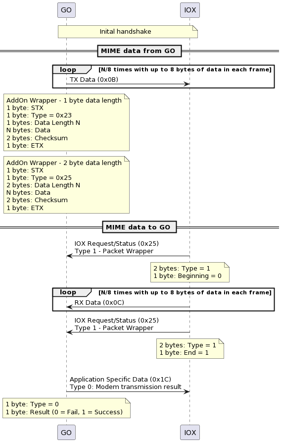
TX Data (0x0B)
Data sent from the GO device to the addressed IOX. The contents of this payload may follow a higher level protocol structure such as MIME.
Payload — TX Data
| Byte # | Byte Description |
|---|---|
| 0-7 | Data to transmit |
RX Data (0x0C)
Data sent from an IOX to the GO device. The GO will reply with an ACK. The contents of this payload may follow a higher level protocol structure such as MIME. The 0x0C message series start and end with a Information Type 1 - Packet Wrapper 0x25 message.
Payload — RX Data
| Byte # | Byte Description |
|---|---|
| 0-7 | Received data |
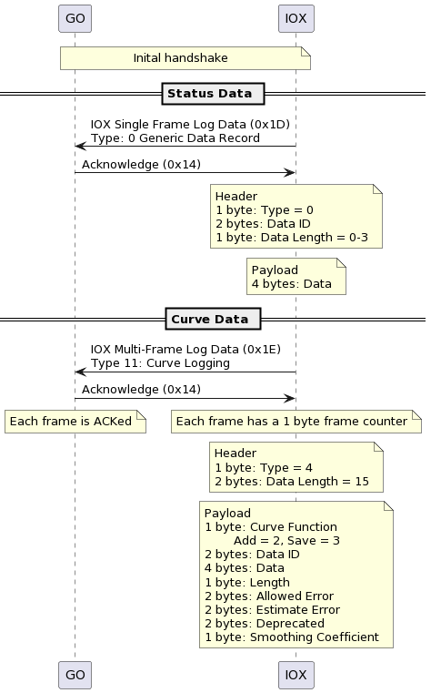
Acknowledge (0x14)
Sent by the GO to indicate that a message is being acknowledged. The ACK to an RX Data message (0x0C) could include 1 byte of data. This data is used for streaming flow control. When the 80% watermark of the receive buffer has been reached, the flow control bit will tell the IOX to hold off sending for 50 ms. The IOX will send the next frame at the end of this period and, depending on the flow control bit of the ACK, it will either continue sending or delay another 50 ms, thus repeating the process. The GO device will clear the flow control bit whenever the buffer is below the 20% watermark. If transferring data as part of a wrapped packet exchange, the streaming watermark can be ignored. The buffers will not overflow so long as the length limit and the modem result are honored. This byte is only sent when needed.
Payload
| Byte # | Byte Description |
|---|---|
| 0 - Bit 0 | 0 = Clear to send more RX Data. 1 = Stop sending UART Data. Buffer 80% full, withhold next frame 50 ms. |
| 1 - Bit 1-7 | Reserved |
Application Specific Data (0x1C)
Sent by the GO device after a packet wrapped passthrough message attempt to the server. A ‘rejected’ response from the modem typically means it is not connected. If the message is ‘accepted’, this means it was added to the modem’s TCP socket buffer. It is NOT a confirmation that the message was successfully sent.
Type 0: Modem Transmission Result
| Byte # | Byte Description |
|---|---|
| 0 | Log Type |
| 1 | 0 = Rejected 1 = Accepted |
IOX Single Frame Log Data (0x1D)
Sent from the IOX to the GO device when the IOX wants to create a log that can fit into a single CAN frame. Rate limit is 100 logs per 10 minutes, for each distinct data ID. If you exceed the rate limit, the GO device will stop taking data from the IOX.
Payload
| Byte # | Byte Description |
|---|---|
| 0 | Log Type |
| 1-7 | Data |
Log Type: 0 (GenericDataRecord)
Used to request the GO log normal status data.
| Data | Description |
|---|---|
| 1-2 | Data ID |
| 3 | Data Length |
| 4-7 | Data |
Log Type: 3 (PriorityDataRecord)
Used to request the GO log status data and also send via Iridium, if available.
| Data | Description |
|---|---|
| 1-2 | Data ID |
| 3 | Data Length |
| 4-7 | Data |
Log Type: 1 (externalDeviceConnectionStatus)
Used to identify the service running on the IOX. Required to use the passthrough channel to communicate with MyGeotab.
| Data | Description |
|---|---|
| 1 | Connected = 1 Disconnected = 0 |
| 2-3 | External Device ID |
| 4-5 | Connection flags |
| Bits | Connection flags |
|---|---|
| 0 | Reserved |
| 1 | Binary Data Packet Wrapping |
| 2 - 15 | Reserved |
Binary Data Packet Wrapping: 0: The passthrough data from MyGeotab will be passed to the external device without modification. 1: The passthrough data from MyGeotab will be wrapped in a serial protocol before being sent to the external device. Note: If sending large payloads of variable sizes, it is recommended to use the binary wrapping flag to allow the device to distinguish and accommodate different packet sizes. The device should implement support for both 0x23 and 0x25 message formats as the GO will dynamically select which one to use based on the amount of data within each packet received from MyGeotab. The maximum packet size currently supported is 1000 bytes.
For payloads with a length of 0 - 255 bytes, this format is used:
| Bytes | Position | |
|---|---|---|
| STX (0x02) | 1 | 0 |
| Message Type = 0x23 | 1 | 1 |
| Message Body Length = x | 1 | 2 |
| Binary Data | x | 3 |
| Checksum | 2 | 3+x |
| ETX (0x03) | 1 | 5+x |
For payloads with a length of 256 - 1000 bytes, this format is used:
| Bytes | Position | |
|---|---|---|
| STX (0x02) | 1 | 0 |
| Message Type = 0x25 | 1 | 1 |
| Message Body Length = x | 2 | 2 |
| Binary Data | x | 4 |
| Checksum | 2 | 4+x |
| ETX (0x03) | 1 | 6+x |
More details on the checksum can be found here: Add-On Protocol - RS232 & USB
Log Type: 2 (GenericFaultRecord)
Typically used to log a fault condition that needs to be escalated to a supervisor for human intervention.
| Data | Description |
|---|---|
| 1-2 | Fault code |
| 3 | Fault = 1 Information = 0 |
| 4 | Log Once Per Trip = 1 Log Every Fault = 0 |
IOX Multi-Frame Log Data (0x1E)
Sent from the IOX to the GO device when the IOX wants create a log that cannot fit into a single CAN frame. The first frame contains the Type and Length. All frames start with a Frame Counter that is an incrementing sequence number. The first frame always starts with 0x00.
Payload First Frame
| Byte # | Byte Description |
|---|---|
| 0 | Frame Counter (0x00) |
| 1 | Log Type |
| 2-3 | Data Length |
| 4-7 | Data |
Payload Subsequent Frames
| Byte # | Byte Description |
|---|---|
| 0 | Frame Counter |
| 1-7 | Data |
Log Types
| Parameter Type | Description |
|---|---|
| 0 | Third Party Free Format Data |
| 1 | Reserved |
| 2 | Bluetooth Record |
| 3-9 | Reserved |
| 10 | Driver ID |
| 11 | Curve Logging |
| 12 | Logging With Timestamp |
| 13 | Protobuf Data |
Type 0 Third Party Free Format Data
The maximum size is 27 bytes. Rate limit is 500 logs per 10 minutes. If you exceed the rate limit, the GO device will stop taking data from the IOX.
| Byte # | Driver ID |
|---|---|
| 0-27 | Data |
Type 2 Bluetooth Record
Rate limit is 1200 logs per 10 minutes. If you exceed the rate limit, the GO device will stop taking data from the IOX.
| Byte # | Bluetooth Record |
|---|---|
| 0-6 | MAC Address |
| 1 | Data Type |
| 2 | FP24 Value |
Further details can be found here: Add-On Protocol - BLE
Type 11 Curve Logging
This message can be used to send the 4-byte (int32_t) data that is curve logged by the GO. Additional information about curve logging can be found here: Curve Logging
| Byte # | Curve Logging |
|---|---|
| 0 | Curve Function |
| 1-2 | Status Data ID |
| 3-7 | Data (signed 32bit) |
| 8 | Data Length |
| 9-10 | Allowed Error |
| 11-12 | Estimate Error |
| 12-13 | Deprecated = 0 |
| 14 | Smoothing Coefficient |
| Parameter | Description |
|---|---|
| Curve Function | 2 = Add Point 3 = Save Curve |
| Allowed Error | Vertical distance threshold (must be > 0). All points with their vertical distance > threshold are declared as significant points and saved. |
| Estimate Error | If EstimateError > 0 and the new point deviated from estimated value > EstimateError, we will reduce/save the curve. |
| Smoothing Coefficient | Applies a low pass filter to the data. 0 = No filtering 1-254 = Smoothing coefficient magnitude |
Type 12 Logging With Timestamp
This message can be used to send status data with a timestamp. Possible use cases:
- Store data in the IOX while the GO device is asleep and send all data after waking up
- Run the curve logging algorithm in the IOX and send those points to be transmitted to MyGeotab.
Additional information about curve logging can be found here: Curve Logging
| Byte # | Curve Logging |
|---|---|
| 0-1 | Status Data ID |
| 2 | Data Length |
| 3-6 | Data (unsigned 32bit) |
| 7 | Timestamp (# secs since 2002-01-01) |
| 8 | Milliseconds |
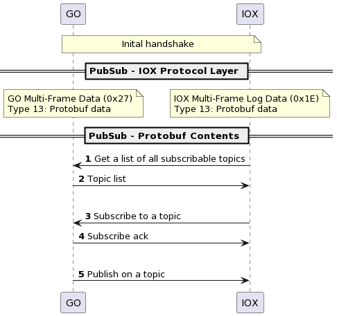
Type 13 Protobuf Data
Supported from Add-On protocol version 1.2.
This message allows an IOX to send a protobuf-encoded payload to the GO device. It supports a publish/subscribe model of vehicle status information. The GO device responds with GO Multi-Frame Data (0x27) - Type 13. Protobuf Schema. The currently supported topics are:
| Topic |
|---|
| TOPIC_VIN |
| TOPIC_GEAR |
| TOPIC_ENGINE_SPEED |
| TOPIC_ENGINE_LOAD |
| TOPIC_ODOMETER |
| TOPIC_ACCEL_PEDAL_PERCENTAGE |
| TOPIC_COOLANT_TEMP |
| TOPIC_DOC_INTAKE_GAS_TEMP |
| TOPIC_DOC_OUTLET_GAS_TEMP |
| TOPIC_FUELTANK1_UNITS |
| TOPIC_FUELTANK2_UNITS |
| TOPIC_FUELTANK1_PERCENT |
| TOPIC_FUELTANK2_PERCENT |
| TOPIC_STATE_OF_CHARGE |
| TOPIC_ENGINE_ROAD_SPEED |
| TOPIC_VEHICLE_ACTIVE |
| TOPIC_DRIVER_SEATBELT |
| TOPIC_LEFT_TURN_SIGNAL |
| TOPIC_RIGHT_TURN_SIGNAL |
| TOPIC_EV_CHARGING_STATE |
| TOPIC_PARK_BRAKE |
Buzzer Beep (0x24)
Sent from an IOX to the GO device to request the buzzer beep with the given parameters.
Payload
| Byte # | Byte Description |
|---|---|
| 0 | Number of Beeps |
| 1 | Duration (Multiple of 56ms) |
| 2 | Delay Between Beeps (Multiple of 56ms) |
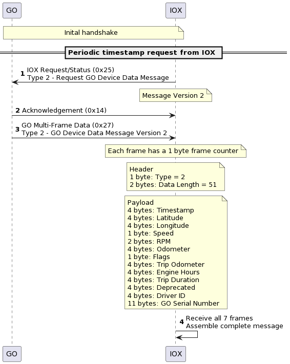
IOX Request/Status (0x25)
Sent from the IOX to the GO device to inform the GO device of events or status changes.
Payload
| Byte # | Byte Description |
|---|---|
| 0-1 | Information Type |
| 2-7 | Optional bytes that depend on the type |
Information Type 0 — Busy
This message indicates to the GO device that the issuing IOX is busy with a critical task and that the GO should not enter the sleep state. The IOX should send a message clearing the flags once it has completed its critical tasks.
| Byte # | Description |
|---|---|
| 0-1 | 0x0000 |
| 2 - Bit 0 | Busy, Request GO stay awake |
| 2 - Bit 1 | Busy, Request GO keep the modem active |
Information Type 1 - Packet Wrapper
This is used to send a packet of up to 1023 bytes of binary data through the GO device to MyGeotab.
Use cases:
- Send Packet Wrapper - Beginning of data packet (0).
- Multiple RX Data (0x0C) messages until the entire bypass binary data is sent. Pay attention to the Acknowledge (0x14) message responded from GO if the GO Receive-Buffer is ready to accept the next RX Data (0x0C) message. The streaming flow control bit in the ACK is not relevant for this type of exchange and can be ignored.
- Send Packet Wrapper - End of data packet (1).
- At the end, GO sends confirmation with a Application Specific Data (0x1C) Type 0 (Modem transmission result) message to indicate if the packet has been accepted within 6 seconds.
| Byte # | Description |
|---|---|
| 0-1 | 0x0001 |
| 2 | 0 = Beginning of data packet 1 = End of data packet |
Information Type 2 - Request GO Device Data Message
This message is used by an IOX which requires vehicle information from the GO device. The GO device responds with a GO Multi-Frame Data (0x27) - Type 2 message.
| Byte # | Description |
|---|---|
| 0-1 | 0x0002 |
| 2 | Message Version = 2 |
Information Type 3 - Connect and Send Records
This message requests the GO modem initiate a connection to the server.
| Byte # | Description |
|---|---|
| 0-1 | 0x0003 |
| 2 | Unused |
Information Type 4 - Request VIN Message
An IOX uses this message to request the vehicle’s VIN from the GO device. The GO device responds with a GO Multi-frame Data (0x27) - Type 3 message.
| Byte # | Description |
|---|---|
| 0-1 | 0x0004 |
| 2 | Unused |
Information Type 12 - Request Identification of Go device, versions
Supported from protocol version 1.1.
Sent from the IOX to the GO device requesting the identification information. The GO device responds with a GO Multi-Frame Data (0x27) - Type 12 message.
| Byte # | Description |
|---|---|
| 0-1 | 0x000C |
| 2 | Request info: 0 = GO serial number 1 = GO firmware version 2 = IOX protocol version |
GO Status Information (0x26)
Sent from the GO device to the IOX to pass information the IOX may need. This is a broadcast message. It is sent once any corresponding information type changes.
Payload
| Byte # | Byte Description |
|---|---|
| 0-1 | Information Type |
| 2-7 | Optional bytes that depend on the type |
Information Type 0 - Ignition
| Byte # | Description |
|---|---|
| 0-1 | 0x0000 |
| 2 | 0 = Ignition Off 1 = Ignition On |
Information Type 1 - Modem Availability
| Byte # | Description |
|---|---|
| 0-1 | 0x0000 |
| 2 | 0 = Modem is not ready 1 = Modem is available |
GO Multi-Frame Data (0x27)
Sent from the GO device to the IOX when the GO device wants to transfer data that does not fit into a single CAN frame. The first frame contains the Type and Length. All frames start with a Frame Counter that is an incrementing sequence number. The first frame always starts with 0x00.
Payload First Frame
| Byte # | Byte Description |
|---|---|
| 0 | Frame Counter (0x00) |
| 1 | Info Type |
| 2-3 | Data Length |
| 4-7 | Data |
Payload Subsequent Frames
| Byte # | Byte Description |
|---|---|
| 0 | Frame Counter |
| 1-7 | Data |
Info Types
| Parameter Type | Description |
|---|---|
| 0 | Reserved |
| 1 | Reserved |
| 2 | GO device data packet |
| 3 | VIN |
| 4-11 | Reserved |
| 12 | GO info |
| 13 | Protobuf Data |
Type 2 GO Device Data
Sent in response to an IOX Request(0x25) message with a Type Request GO Device Data Message (0x02).
| Bytes | GO Device Data |
|---|---|
| 0-3 | Timestamp (# secs since 2002-01-01) |
| 4-7 | Latitude (1E-7 deg/bit) |
| 8-11 | Longitude (1E-7 deg/bit) |
| 12 | Road Speed (km/hr) |
| 13-14 | RPM |
| 15-18 | Odometer (0.1 Km/bit) |
| 19 | Status Flags (from LSB): 1st bit: 1 = GPS Valid 2nd bit: 1 = Ignition On 3rd bit: 1 = Engine Bus Activity 4th bit: 1 = Date/Time Valid 5th bit: 1 = Speed From Engine 6th bit: 1 = Odometer From Engine |
| 20-23 | Trip Odometer (0.1 Km/bit) |
| 24-27 | Total Engine Hours (0.1 hours/bit) |
| 28-31 | Trip Duration (1 second/bit) |
| 32-35 | Deprecated |
| 36-39 | Driver ID |
| 40-51 | GO Device Serial Number |
Type 3 VIN
Sent in response to an IOX Request(0x25) message with Type Request VIN (0x04).
| Bytes | GO Device Data |
|---|---|
| 0-16 | VIN |
Type 12 GO Info
Supported from protocol version 1.1. Sent in response to IOX Request/Status (0x25) - Type 12.
payload id = 0
| Byte | Byte Description |
|---|---|
| 0 | =0 for payload is GO serial number. |
| 1-12 | GO serial number |
| 13 | 0 |
payload id = 1
| Byte | Byte Description |
|---|---|
| 0 | =1 for payload is GO firmware version number. |
| 1-2 | GO firmware version: Product |
| 3-4 | GO firmware version: Major |
| 5-6 | GO firmware version: Minor |
payload id = 2
| Byte | Byte Description |
|---|---|
| 0 | =2 for payload is IOX protocol version number. |
| 1-2 | GO firmware version: Major |
| 3-4 | GO firmware version: Minor |
Type 13 Protobuf Data
Supported from protocol version 1.2.
This message allows a GO device to send a protobuf-encoded payload to the IOX. It supports a publish/subscribe model of vehicle status information. It is a response to GO Multi-Frame Data (0x1E) - Type 13. Protobuf Schema.
Sequence Diagrams
Handshake
Sleep/Wake
Data Logging
GO Info
PubSub
MIME