IOX Add-On Hardware Design Guide
System Introduction
The GO Device is a small yet extremely powerful telematics measurement device. It offers Geotab IOX® expandability for hardware Add-Ons, which could be provided by Geotab or a third party.
This hardware design guide is suggested reading for any third-party manufacturer who wants to design and build devices that integrate with the GO Device. For more information on the IOX communication protocols, see the IOX Protocol document.
Hardware Structure
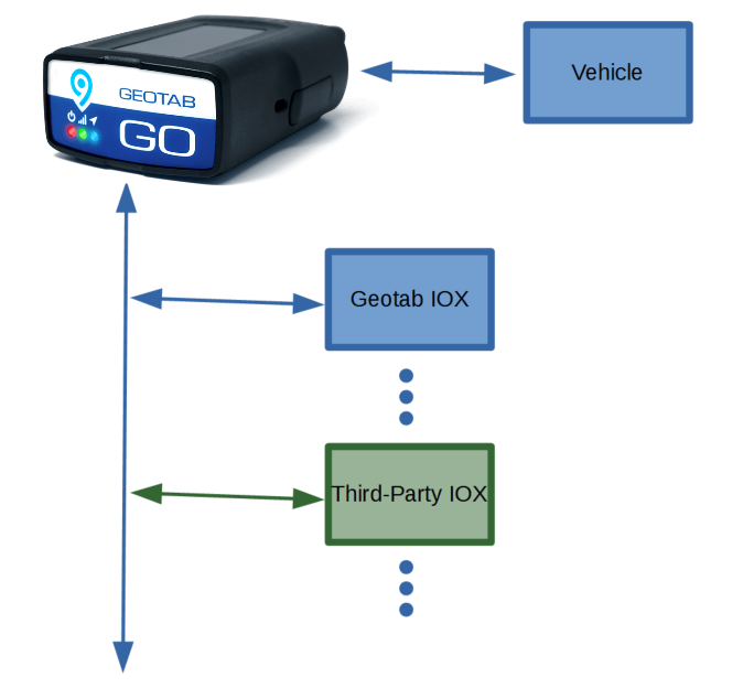
The third-party device can get 12 V/24 V power from the GO Device, communicate with the GO Device through the CAN bus, and perform its specific service for end customers.
The GO Device provides a mini-B USB receptacle for connecting IOXs and third-party devices. This USB receptacle does not carry USB signals or power, but does provide the CAN bus and power from the vehicle. Two small plastic guards are placed around this receptacle to prevent misinsertion of a real USB plug. The corresponding connector on an IOX or a third-party device should be a mini-B USB plug.
Multiple IOXs can be connected to the GO Device through a daisy chain configuration. The IOX device itself has a mini-B USB receptacle that can provide CAN bus and power from the vehicle to the next device in the chain.
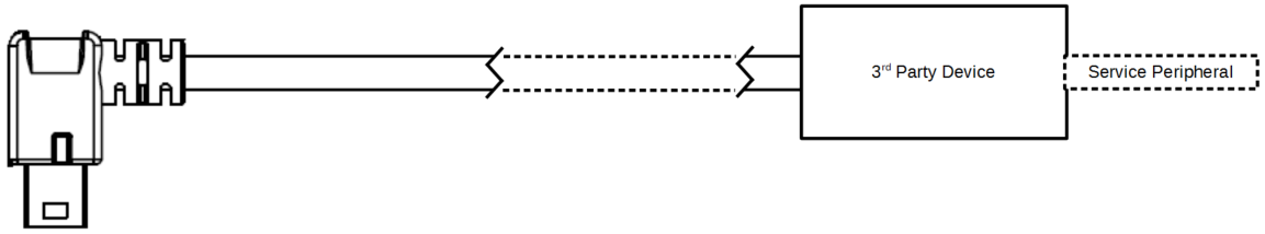
A mini-B USB receptacle needs to be added to a third-party device if this third-party device is not meant to be the last device in a daisy chain or if more than one third-party device will be used in the chain.
Mini-B USB Plug Input
The diagram and table below provides pin numbering and definitions.
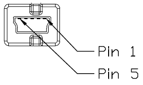
| Pin No. | Definition | Note |
|---|---|---|
| 1 | NC | This pin must be left unconnected |
| 2 | CAN− | |
| 3 | CAN+ | |
| 4 | GND | |
| 5 | Power |
Power Design
The GO Device provides overvoltage protection, undervoltage protection, and overcurrent protection for the battery power supply to the IOX interface.
The third-party device must work properly with a power input voltage range between 6 V and 33 V.
A current of up to 3 A could be supplied from the GO Device to be shared by all the IOX devices in the daisy chain. It is suggested that the current consumption be limited to 2.5 A for one third-party device if the device is the only one connected to the GO Device. The maximum current should be calculated during hardware design if more than one devices is intended to be in the daisy chain. The GO Device will cut off power if the current exceeds 3 A for more than 18.6 ms (minimum).
Reverse current to the power line must be prevented, for which a diode on the power input would be sufficient.
The third-party device must enter Sleep Mode when notified by the GO Device or when it fails to communicate with the GO Device after a reset. The current of the device in Sleep Mode should not exceed 2 mA at 12 V. The prefered Sleep Mode current is below 0.4 mA.
CAN Bus Communication
The CAN controller should support CAN 2.0B @ 500 kbps.
The CAN transceiver must be compatible with ISO 11898. SAE J2284 and GMW3122 are optional, but better to have. Suggested parts at the time of writing are Atmel ATA6561, NXP TJA1042TK/3, Microchip MCP2562T and TI TCAN1042.
The CAN transceiver should enter Standby Mode to save power when the device is in Sleep Mode. In Standby Mode, the receiver either remains active or RXD is with Wake-Up Request function (A wake-up request is output to RXD (driven low) for any dominant bus transmissions longer than a filter time.) Correspondingly, the MCU should have ability to be woken up by a CAN message or an external interrupt.
A 120-ohm differential impedance must be implemented for the CAN bus in the design of the PCB. If the third-party device is designed without a USB receptacle, a 120-ohm terminal resistor should be added to the CAN bus, otherwise the CAN bus terminal resistor is not allowed on the board.
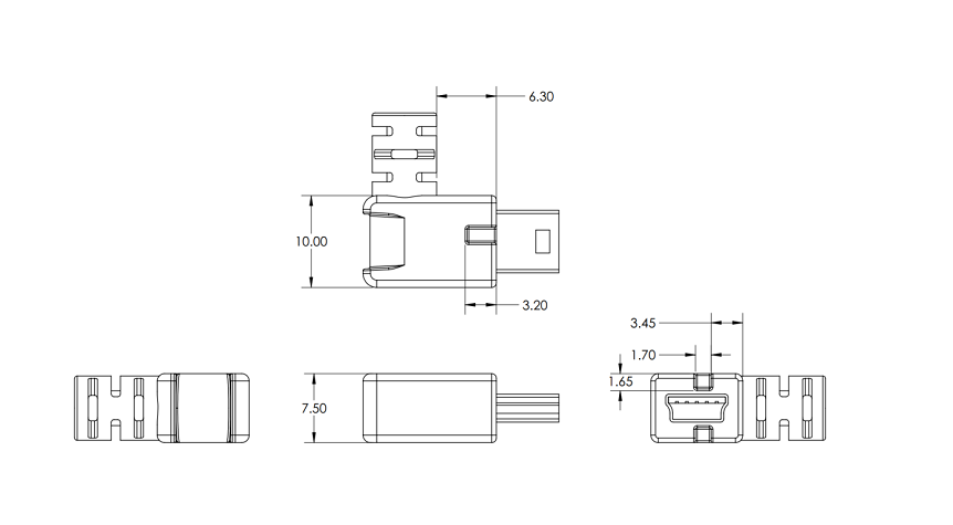
Mechanical Design
Below is the mechanical size for a USB mini-B plug of the IOX device. All dimensions are given in mm.
The suggested cable length is between 30 cm to 100 cm, which is based on the multiple devices in the daisy chain. The length of cable may be longer if the system of the application is with fewer devices. The positive and negative wire of the CAN bus need to be a twisted pair with inner shielding around just them, with a minimum twisting ratio is 1 twist every 25.4 mm.
It is suggested that you shield the whole wires and that you short the drain wires of both shields (the shield for whole wires and the shield for the CAN bus) to the metal body of the USB plug.
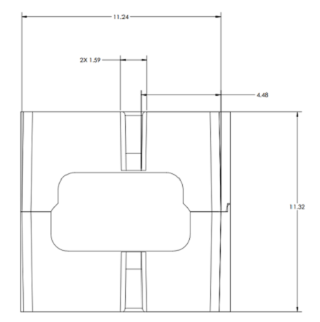
Below is the mechanical size for a USB mini-B socket of the IOX device. All dimensions are given in mm.
It is suggested that an IOX socket is included where possible so additional IOX devices can be daisy chained.